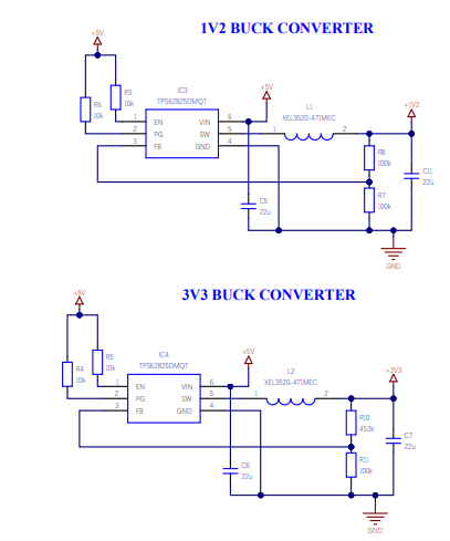
When I am not having fun creating Hackster projects or presenting webinars, I earn a living working on client-facing projects. Most of my client projects are high reliability, mission-critical systems, so designing these systems brings new challenges and requires a significant element of design analysis.

One design analysis technique used when designing these types of systems is to perform a Part Stress analysis. This analysis examines each component in the system to determine its electrical and thermal stresses. Higher stresses on the device, even if within the component’s operating conditions, can affect the overall system reliability.
Components fail when the stresses placed on them exceed their strength. Derating the maximum stresses placed on the component provides safety margins for the design.
In short, operating components at or above their rated operational maximum can shorten the life of those components and the overall system.
We can also use the same technique in commercial designs to ensure we achieve the best possible reliability. Although in these cases, we do not have to stick to the rules quite so rigidly or get sign off if the stresses are above those allowed, as long as they are still acceptable for the application.
When we perform a Part Stress analysis, we are checking that each component has been appropriately derated. The derating rules used may be supplied by the client and be bespoke. Alternatively, they will use a formal standard such as the following:
Mil-STD-975 – NASA
Mil-STD-1547 – DoD
AS4613 – US Navy
Nav Sea TE000-AB-GTP-010 – US Navy
ESCC-Q-30-11A – ESA
MSFC-STD-3012 – NASA Marshall Space Centre
These standards will define several derating parameters that must be applied to different component types, like using the ESA specification, for example.

Performing the derating analysis can take considerable time depending on the circuit size because we need to examine every element of the circuit and calculate the stresses.
If we identify components which exceed the allowable stresses, we have two available options:
Decrease the stress applied to the component (e.g., by distributing it across several components).
Increasing the rating of the component which often needs a larger component to be selected.

With discrete components such as R, C, L, and transistors etc., we can often easily reduce the stresses by distributing the stress across other components.
A linear regulator, for example, will dissipate too much power in the pass transistor to achieve the derating requirements. We can lower the voltage supplied to the linear regulator using low-value resistors to reduce the voltage drop across the pass transistor. We still dissipate the same power; it’s just spread over several components and distributed over the board. This is often done when the component choice is limited as it can be with space and high reliability components.
Of course, such an approach cannot be undertaken with high-performance components such as processors or FPGAs. Here, the main derating challenge is ensuring that the junction temperature is below what is allowed by the derating standard. Of all the derating challenges, the junction temperature is the hardest to achieve because it needs to consider the operating conditions (e.g., maximum operating temperature).
With processors and programmable logic, the ability to accurately estimate the power dissipation is key. This power estimation could be from simulations and power estimation as is the case with programmable logic or power estimation spreadsheets and models for processors.
In these devices, we can reduce the junction temperature by deploying power-saving modes or employing low power modes or implementing power-reducing strategies in programmable logic (e.g., clock gating of unused elements).
We can also use thermal techniques such as heat sinks and micro heat pipes which conduct heat to the structure. One solution that may look like a quick fix is to use a fan, but this often introduces a weak point in the system and often the fan fails.
Regardless of if you are performing a high reliability / mission-critical design or not. Derating your components and doing a simple Part Stress Analysis can help you create a solution that does not experience random failures due to failing components and the associated stress and reputational impact.
Note - If you missed my talk about an introduction to high reliability design which talks about not only derating but also system level issues, challenges and FPGA design mitigation techniques you can watch the on demand video here.

Comments