One of the devices we often use for our client space projects is the PolarFire and PolarFire SoC.

Over the years we have done several developments based around these devices, typically these are for imaging based payloads. Generally for prototyping we use either the Icicle board for SoC designs or the PolarFire Video kit if a FPGA is required.
When the Discovery Kit was announced, I decided to purchase a couple as they look interesting for prototyping SoC designs.
In this blog we are going to take a look at creating a simple program running on the RISCV cores.
To do this we will need the following
Soft Console: https://www.microchip.com/en-us/products/fpgas-and-plds/fpga-and-soc-design-tools/soc-fpga/softconsole
Discovery Kit References: https://github.com/polarfire-soc/polarfire-soc-discovery-kit-reference-design
Bare Metal Examples: https://github.com/polarfire-soc/polarfire-soc-bare-metal-examples
You will also need a free libero license which can be obtained here
To get started we first need to create a hardware definition, this hardware definition will define not only the logic design implemented within the fabric. But also the configuration of the processor sub system which contains the five RISCV processors and supporting peripherals.
The first step is to create a new project, saving it in a location you desire.

Select MPFS095T in a FCSG325 Package and speed grade 1.

Leave the defaults unchanged.

We also have no RTL or constraints files to add.


Once the project is created the next step is to create a Smart Design, this is the visual top level of where we will be instantiating the processor system configuration along with any logic designs.

The next step is to open the PolarFire SoC MSS Configurator. This is a stand alone tool you can find in the installation directory of libero. We use this tool to configure the processor sub system and generate the outputs.

First however we need to load in the configuration file for the discovery board. The files downloaded earlier from the Discovery Kit References under the script support directory will contain a file called MPFS_DISCOVERY_KIT_MSS.cfg.
This is the configuration file to load, once loaded it will show the current set up of the discovery kits processor system.

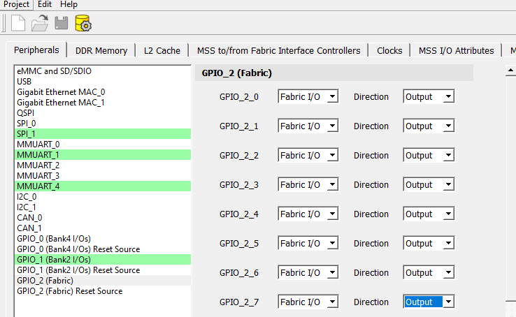
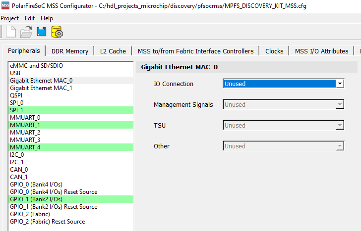
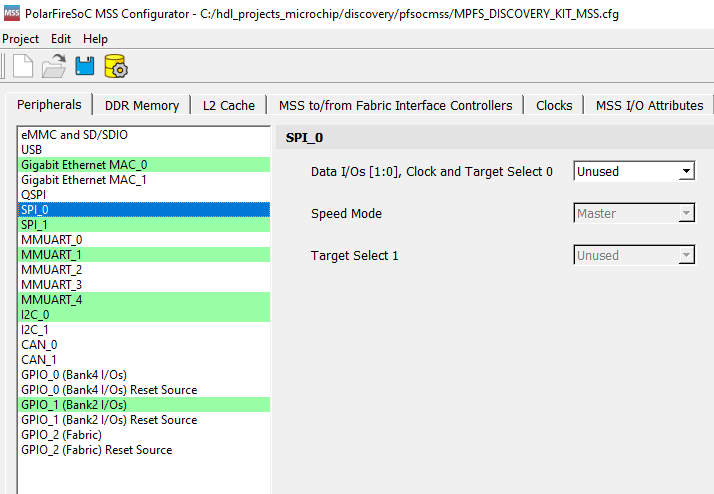
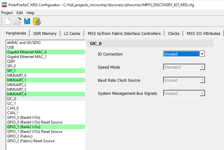
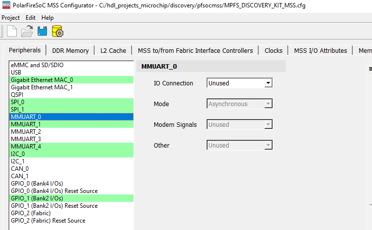
For this system we are going to create a minimal solution as such many of the interfaces which connect with the fabric we will disable. The exception will be the LEDS as we need something in the fabric to ensure Synplify correctly synthesises the project.
Configure the system as shown in the gallery of images below, this disables all of the fabric interfaces except for the LED interfaces.
Once this is completed save the file and generate the outputs, select a directory separate from the discovery downloads.

Back in Libero, click on import MSS and select the directory you just exported the design into and select the CXZ file.

On the design tab you will then see the top_level and the component, right click on the MSS component and select instantiate in smart design.

Onto this diagram we need to promote the LED outputs to the top level
and tie off the reset pin high.

Once this is created the next step is to generate the smart design which will create the RTL for synthesis.
To be able to complete the flow however, we need first enter the pin constraints for the LEDS. From the constraints manager view.

Select new and create a new constraints PDC.

Enter the pin locations for the LEDS
set_io -port_name LED0  \
    -pin_name T18       \
    -fixed true         \
    -DIRECTION OUTPUT


set_io -port_name LED1  \
    -pin_name V17       \
    -fixed true         \
    -DIRECTION OUTPUT


set_io -port_name LED2  \
    -pin_name U20       \
    -fixed true         \
    -DIRECTION OUTPUT


set_io -port_name LED3  \
    -pin_name U21       \
    -fixed true         \
    -DIRECTION OUTPUT


set_io -port_name LED4  \
    -pin_name AA18      \
    -fixed true         \
    -DIRECTION OUTPUT


set_io -port_name LED5  \
    -pin_name V16       \
    -fixed true         \
    -DIRECTION OUTPUT


set_io -port_name LED6  \
    -pin_name U15       \
    -fixed true         \
    -DIRECTION OUTPUT
Once these are entered we can generate the programming file, connect the discovery board to our development board and program the board.
This leaves us in a position to be able to create the SW application. For this we will be using soft console and the bare metal examples downloaded from the git repo.
The first thing to do is create a new workspace. Once soft console is open we are going to, import an example design from the bare metal repo. This has several examples which are compatible with the discovery board.

For this example I am going to import the GPIO Interrupt example which is located under the driver examples directory.

Once the project is imported, from the build configurations I selected the debug Discovery Kit option.

Clicking the hammer will then build the application, you should see the resulting build information in the transcript.

Once we have the executables, we are able to download and execute the applications on the PolarFire SoC.
Select debug configurations and all harts and click debug.

This will download the application and pause the execution of the processors, ensure you have serial terminal open (115200N1) and click on the run icon to run the processors.

You should see in the resultant window you should see the output of the applications executing.

There we have it a simple hello world walk through.
Workshops and Webinars
If you enjoyed the blog why not take a look at the free webinars, workshops and training courses we have created over the years. Highlights include
Upcoming Webinars Timing, RTL Creation, FPGA Math and Mixed Signal
Professional PYNQ Learn how to use PYNQ in your developments
Introduction to Vivado learn how to use AMD Vivado
Ultra96, MiniZed & ZU1 three day course looking at HW, SW and PetaLinux
Arty Z7-20 Class looking at HW, SW and PetaLinux
Mastering MicroBlaze learn how to create MicroBlaze solutions
HLS Hero Workshop learn how to create High Level Synthesis based solutions
Perfecting Petalinux learn how to create and work with PetaLinux OS
Boards
Get an Adiuvo development board
Adiuvo Spartan 7 / RPi 2040 Embedded System Development Board
Adiuvo Spartan 7 Tile - Low Risk way to add a FPGA to your design.
Embedded System Book
Do you want to know more about designing embedded systems from scratch? Check out our book on creating embedded systems. This book will walk you through all the stages of requirements, architecture, component selection, schematics, layout, and FPGA / software design. We designed and manufactured the board at the heart of the book! The schematics and layout are available in Altium here Learn more about the board (see previous blogs on Bring up, DDR validation, USB, Sensors) and view the schematics here.






コメント