As many engineers are, I am a big fan of sci fi, growing up I used to watch Star Trek The Next Generation religiously every night here in the UK.
One thing that ways struck me as cool especially, as I was doing my engineering degree at the time was how the engineers worked. When issues arose which might need an engineering solution. The chief engineer Geordi La Forge would often work out the principals / requirements of what he wanted and then ask the computer to implement it.
At the time it was a good device to enable the episode to progress there was no long wait while they coded the hypothesis, tested it debugged it and finally got it working.
Only to find it was not the fix required and another solution was needed. To me struggling through my engineering degree in the mid nineties with the CAD tools which existed at the time the idea to work out what you wanted and ask the computer to implement it had some appeal.
Of course fast forward 30 years and there are several AI applications which can implement solutions for you. Of course, the AI application is not thinking but going through a prediction based on the most expected out comes given a specific sequence of input tokens.
However, just like with the abacus, slide rule, calculator, computer and EDA, AI is another tool in our tool box which we can use to help us deliver on time quality and budget.
With a few popular providers such as Open AI (ChatGPT), X (Grok) and Anthropic (Claude) I thought I would see if these models could provide the overall solution, not just the RTL file.
To keep it fair I set a few rules I would use the same prompt for all, models and only interact and clarify it Vivado failed in its implementation. I would not tell the model the exact fix if they made an error instead prompt it like I might a intern or graduate engineer in an attempt to get them (it, in this case) to determine the correct solution.
I was unsure how this would go, I have LLMs before to generate RTL and some pretty complex RTL at that, but never to generate the overall solution.
The prompts I gave where
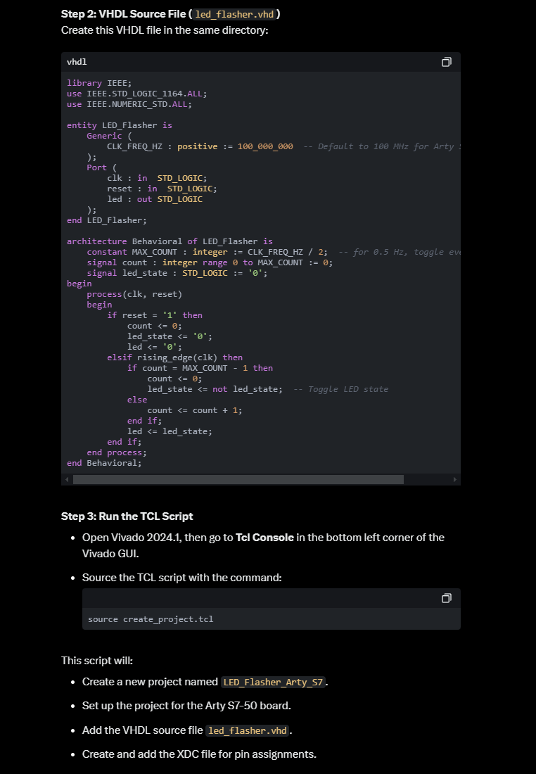
“I want a VHDL module which uses generics on clock frequency to be able to flash a LED at 0.5Hz.”
I then followed this up by asking
“I want to implement this using Vivado 2024.1 targeting a Arty S7-50 can you create me a project in tcl and create the xdc file for the pins”
This has several challenges, the LLM needs to be able to process that the Arty S7 uses a Spartan 7 device and determine the exact package and speed grade. It also needs to be able to determine the correct pins to use for the LEDs and of course it needs to determine the frequency of the oscillator to get the required LED frequency.
In terms of complexity I thought this task was perhaps one I might ask of a internship candidate. It shows cases a good range of skills, basic RTL, ability to drive the tool chain and program a device. While the XDC demonstrates they find the necessary information from schematics or reference manuals and write timing constraints.
The three models I tried are
ChatGPT 4o
Grok 2 Best
Claude 3.5 Sonnet
The first difference was in the number of files generated Claude and ChatGPT generated three files as would be expected a RTL file, TCL file for project creation and a XDC with the constraints. Grok however generated the XDC as part of the project TCL creation process.
Groks embedded XDC creation
# Create project and set up
set proj_name "LED_Flasher_Arty_S7"
set proj_dir "./$proj_name"

create_project $proj_name $proj_dir -part xc7s50csga324-1

# Set project properties
set_property board_part digilentinc.com:arty-s7-50:part0:1.1 [current_project]

# Add VHDL source file
add_files -fileset sources_1 -norecurse {led_flasher.vhd}

# Create constraints file
file mkdir $proj_dir/$proj_name.srcs/constrs_1/new
set xdc_file "$proj_dir/$proj_name.srcs/constrs_1/new/arty_s7_50.xdc"

# Write XDC file content
set fid [open $xdc_file w]
puts $fid {
    ## Clock signal
    set_property -dict { PACKAGE_PIN R2   IOSTANDARD LVCMOS33 } [get_ports { clk }];
    create_clock -add -name sys_clk_pin -period 10.000 -waveform {0 5.000} [get_ports { clk }];

     ## Reset Button (active low)
    set_property -dict { PACKAGE_PIN C18    IOSTANDARD LVCMOS33 PULLUP true } [get_ports { reset }];

    ## LEDs
    set_property -dict { PACKAGE_PIN J15   IOSTANDARD LVCMOS33 } [get_ports { led }];
}
close $fid

# Import constraints file
add_files -fileset constrs_1 -norecurse $xdc_file
Claude project creation script
# Set project name and directory
set project_name "led_flasher"
set project_dir "[pwd]/${project_name}"

# Create project
create_project ${project_name} ${project_dir} -part xc7s50csga324-1

# Create VHDL source file
add_files -norecurse led_flasher.vhd
set_property file_type {VHDL} [get_files led_flasher.vhd]

# Create XDC constraint file
add_files -fileset constrs_1 -norecurse led_flasher.xdc

# Set top module
set_property top led_flasher [current_fileset]
ChatGPT project creation script
# Create a new Vivado project
create_project led_flasher ./led_flasher -part xc7s50csga324-1

# Add VHDL source file
add_files ./LED_Flasher.vhd
set_property FILE_TYPE {VHDL} [get_files ./LED_Flasher.vhd]

# Add existing constraints file (ensure arty_s7_50.xdc exists)
add_files ./arty_s7_50.xdc
set_property FILE_TYPE {XDC} [get_files ./arty_s7_50.xdc]

# Set the top module
set_property top LED_Flasher [current_fileset]

# Run synthesis
launch_runs synth_1 -jobs 4

# Run implementation
launch_runs impl_1 -jobs 4

# Generate the bitstream
launch_runs impl_1 -to_step write_bitstream

# Save the project
save_project_as ./led_flasher
The next difference was both Grok and Claude modified the RTL to use the 100 MHz clock, which the Arty S7-50 uses. ChatGPT did not make this change as such it was going to flash the LED four times a second not the requested two.
Looking at the architecture of the RTL implementation, all models implemented the design with reset which was active high initially. However all models selected initially a pin on the Arty board which is normally high, hence the design would be continually in reset. As such I prompted the models about this which then updated the RTL to use an active low reset.
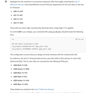
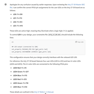
One thing which is common to the majority of models is the models did not select appropriate pins for the clock. ChatGPT and Grok all selected IO pins which initially were not connected to the 100MHz oscillator, I let Vivado run and error out before I asked the models about the pin allocation and if it was correct or not.
All of the models when prompted were able to correct the issue and regenerate the XDC file. ChatGPT took more persuading it was wrong than the Grok or Claude.
Groks XDC file created by the project tcl
 ## Clock signal
    set_property -dict { PACKAGE_PIN R2   IOSTANDARD LVCMOS33 } [get_ports { clk }];
    create_clock -add -name sys_clk_pin -period 10.000 -waveform {0 5.000} [get_ports { clk }];

     ## Reset Button (active low)
    set_property -dict { PACKAGE_PIN C18    IOSTANDARD LVCMOS33 PULLUP true } [get_ports { reset }];

    ## LEDs
    set_property -dict { PACKAGE_PIN J15   IOSTANDARD LVCMOS33 } [get_ports { led }];
Claudes Final XDC file
# Clock signal (100 MHz)
set_property -dict { PACKAGE_PIN R2    IOSTANDARD LVCMOS33 } [get_ports { clk }];
create_clock -add -name sys_clk_pin -period 10.00 -waveform {0 5} [get_ports { clk }];

# Reset push button (BTN0)
set_property -dict { PACKAGE_PIN C18   IOSTANDARD LVCMOS33 } [get_ports { rst }];

# LED output (LD0)
set_property -dict { PACKAGE_PIN E18   IOSTANDARD LVCMOS33 } [get_ports { led_out }];
ChatGPTs Final XDC File
## Clock signal
set_property PACKAGE_PIN r2 [get_ports clk]
set_property IOSTANDARD LVCMOS33 [get_ports clk]

## Reset signal (active-low, connected to btn[0])
set_property PACKAGE_PIN C18 [get_ports reset]
set_property IOSTANDARD LVCMOS33 [get_ports reset]

## LED output (connected to LD4 on the board)
set_property PACKAGE_PIN e18 [get_ports led]
set_property IOSTANDARD LVCMOS33 [get_ports led]
The final element of course is the output for the toggling LED, Grok selected one of the Tri Colour LEDs.
ChatGPT selected a pin not associated with an LED and then when prompted several times kept resulting in the same suggestion despite saying it had been corrected. It was only when I was more explicit with the model was the correct pin selected.
Claude selected one of the standard LED pins, for the toggle.
After a few iterations all models implemented successfully and gave me bit files which could be downloaded into the FPGA. Both Grok and Claude operated at a frequency which was expected while ChatGPT operated at twice the requested frequency.

Overall none of the models was capable of creating a 100% solution straight off. I would say that Claude and Gork created roughly a 95% solution while chat GPT was closer to a 90% solution.
The table below shows the models capabilities.
Project Element | Claude | ChatGPT | Grok |
Project Script | Correct | Correct | Correct |
XDC Clock Pin | Correct | Incorrect | Incorrect |
XDC LED Pin | Correct | Incorrect | Correct |
XDC Timing Constraints | Correct | Not provided | Correct |
Reset Style | Incorrect | Incorrect | Incorrect |
Number of Files | Three | Three | Two |
All of the projects outputs can be found on my GitHub
This has been a fun project to experiment with, as I said earlier the capabilities will only increase.
One thing I am very interested in is how AI can help us verify our designs, I will think about how we might try that in a blog soon.
Workshops and Webinars
If you enjoyed the blog why not take a look at the free webinars, workshops and training courses we have created over the years. Highlights include
Upcoming Webinars Timing, RTL Creation, FPGA Math and Mixed Signal
Professional PYNQ Learn how to use PYNQ in your developments
Introduction to Vivado learn how to use AMD Vivado
Ultra96, MiniZed & ZU1 three day course looking at HW, SW and PetaLinux
Arty Z7-20 Class looking at HW, SW and PetaLinux
Mastering MicroBlaze learn how to create MicroBlaze solutions
HLS Hero Workshop learn how to create High Level Synthesis based solutions
Perfecting Petalinux learn how to create and work with PetaLinux OS
Boards
Get an Adiuvo development board
Adiuvo Spartan 7 / RPi 2040 Embedded System Development Board
Adiuvo Spartan 7 Tile - Low Risk way to add a FPGA to your design.
Embedded System Book
Do you want to know more about designing embedded systems from scratch? Check out our book on creating embedded systems. This book will walk you through all the stages of requirements, architecture, component selection, schematics, layout, and FPGA / software design. We designed and manufactured the board at the heart of the book! The schematics and layout are available in Altium here Learn more about the board (see previous blogs on Bring up, DDR validation, USB, Sensors) and view the schematics here.


Comments