
Next to a simple register, a shift register is one of the simplest synchronous structures we may want to include within our FPGA designs.
While simple, there are several use cases within our designs, from edge detection on signals, balancing pipeline delays, and implementing communication protocols such as UART, SPI, and I2C. Often, these shift registers used for communication protocols also use a clock enable to shift data in or out of the shift register at a lower frequency than the main clock frequency.
At the simplest level, these registers are connected registers. However, how we connect these registers can significantly impact resource utilization. This also ties back to understanding the AMD Ultrafast Design Methodology.
If we implement shift registers as discrete registers within the target device, this will use the registers available within the Configurable Logic Block (CLB) slices, where each slice contains eight registers that can be set or reset. Within each slice, there are eight registers, which can be set or reset.
It is these registers that the synthesis tool uses to implement shift registers. If a set or reset is applied, this can significantly impact performance. This can significantly impact the performance of the design, as the routing between registers will limit clock rates.
library ieee;
use ieee.std_logic_1164.all;
entity shift_example is port (
    i_clk : in std_logic;
    i_rst : in std_logic;
    i_ip  : in std_logic;
    o_op  : out std_logic);
end entity;

architecture rtl of shift_example is

signal s_input : std_logic_vector(31 downto 0);

begin

process(i_clk, i_rst)
begin
    if i_rst = '1' then
        s_input <= (others => '0');
    elsif rising_edge(i_clk) then
        s_input <= s_input(s_input'high-1 downto s_input'low) & i_ip;
  end if;
end process;
o_op <= s_input(s_input'high);

end architecture;
This syntheses as a structure below of flip flops connected as a shift register.
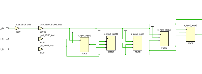
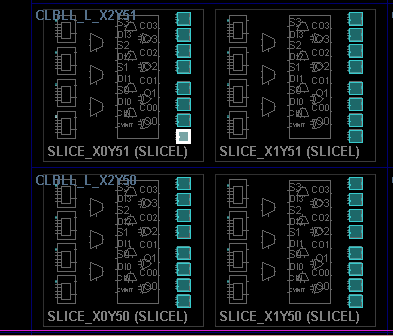
While the implementation in the device shows the use of flip flops in the slices.
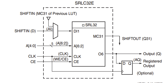
However, if we do not use set/reset on the registers, we can leverage the SliceM function generator to implement a 32-bit shift register. Remember, in 7-series devices, there are two types of slices: SliceL and SliceM. While both can implement function generation, SliceM CLBs can also implement distributed memory and, by extension, fixed and variable-length shift registers.
We can further split this SRL32 into two separate SRL16s, which implement two 16-bit shift registers within a single function generator.
We can implement the shift register in two different ways: we can write our code in a manner that allows the synthesis tool to infer an SRL within a SliceM, as shown below.
library ieee;
use ieee.std_logic_1164.all;
entity shift_example is port (
i_clk : in std_logic;
i_ip : in std_logic;
o_op : out std_logic);
end entity;
architecture rtl of shift_example is
signal s_input : std_logic_vector(31 downto 0);
begin
process(i_clk)
begin
if rising_edge(i_clk) then
s_input <= s_input(s_input'high-1 downto s_input'low) & i_ip;
end if;
end process;
o_op <= s_input(s_input'high);
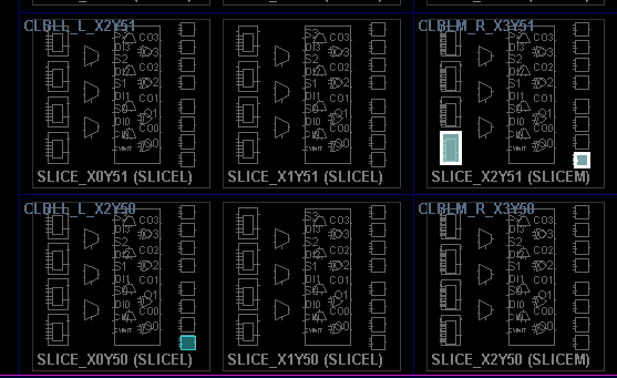
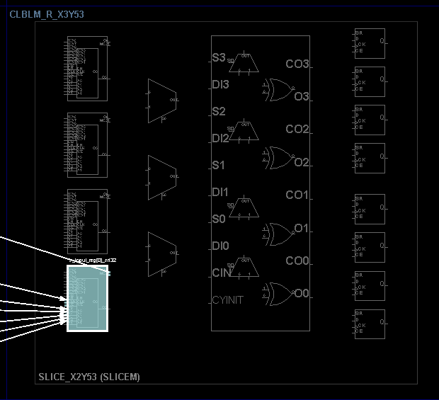
end architecture;Looking at the implementation shows the SliceM being used to implement a a SRL for 30 of the 32 elements in the shift register.
If we want to set or reset the entire shift register to an initial value or pattern, we can leverage the initialization capabilities of our chosen language.
The other alternative to inference is, of course, instantiation. In this case, we can leverage the language templates from within Vivado.
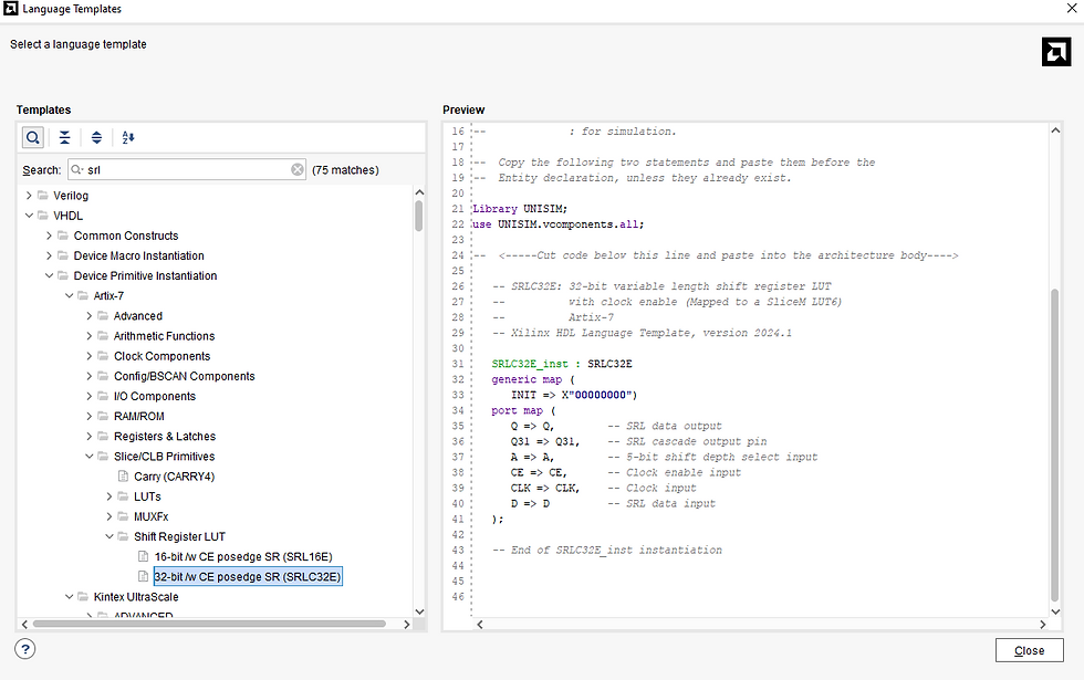
To calculate the depth of the desired SRL, we use the address pins. By setting the address pins to a specific value, we define the depth of the shift register:
Depth = (16 x A4) + (8 x A3) + (4 x A2) + (2 x A1) + A0 + 1
If the address is set to 0000, the delay is one clock cycle from input to output. Hence, set the address to the required delay minus one.
The final element of shift registers to examine in this article is variable-length shift registers, which are adjustable at run time. In this instance, we can change the delay of the shift register dynamically during operation.
If we want to instantiate a variable-length shift register, we can use code like the example below:
library ieee;
use ieee.std_logic_1164.all;
use ieee.numeric_std.all;

entity shift_example is port (
    i_clk : in std_logic;
    i_lng : in std_logic_vector(4 downto 0);
    i_ip  : in std_logic;
    o_op  : out std_logic);
end entity;
architecture rtl of shift_example is
signal s_input : std_logic_vector(31 downto 0);
begin
process(i_clk)
begin
    if rising_edge(i_clk) then
        s_input <= s_input(s_input'high-1 downto s_input'low) & i_ip;
   end if;
end process;
o_op <= s_input(to_integer(unsigned(i_lng)));
end architecture;
Here we can see in the SliceM implemenation of the variable length shift register using the SRL32.
Several times throughout this article, I have mentioned inference or instantiation. Whenever possible, I believe inference is the best approach, as it makes the code more readable and portable.
While this is a relatively simple topic, it is one I still occasionally see implemented incorrectly, often because designers have not read the Ultrafast Design Methodology guide. As such, I think a little refresher from time to time is worthwhile.
Workshops and Webinars
If you enjoyed the blog why not take a look at the free webinars, workshops and training courses we have created over the years. Highlights include
Upcoming Webinars Timing, RTL Creation, FPGA Math and Mixed Signal
Professional PYNQ Learn how to use PYNQ in your developments
Introduction to Vivado learn how to use AMD Vivado
Ultra96, MiniZed & ZU1 three day course looking at HW, SW and PetaLinux
Arty Z7-20 Class looking at HW, SW and PetaLinux
Mastering MicroBlaze learn how to create MicroBlaze solutions
HLS Hero Workshop learn how to create High Level Synthesis based solutions
Perfecting Petalinux learn how to create and work with PetaLinux OS
Boards
Get an Adiuvo development board
Adiuvo Spartan 7 / RPi 2040 Embedded System Development Board
Adiuvo Spartan 7 Tile - Low Risk way to add a FPGA to your design.
Embedded System Book
Do you want to know more about designing embedded systems from scratch? Check out our book on creating embedded systems. This book will walk you through all the stages of requirements, architecture, component selection, schematics, layout, and FPGA / software design. We designed and manufactured the board at the heart of the book! The schematics and layout are available in Altium here Learn more about the board (see previous blogs on Bring up, DDR validation, USB, Sensors) and view the schematics here.
I encountered an interesting situation once where I had to turn off SRL inference in synthesis settings to pass timing. This allowed me to get a float multiplier from 400 to 480MHz on Artix. I believe the reason was the extra individual registers gave the router more flexibility.