A couple of weeks ago I started exploring, fixed and floating point math and the differences between them in FPGA implementations. Of course when targeting 7 Series and UltraScale+ devices the difference between fixed and floating point was as expected considerable.
At the end of the blog I mentioned the DSP58 in versal was capable of implementing floating point using FP32 however, it could not be inferred, it had to be instantiated. As such we followed up exploring how the same floating point algorithm could be implemented using Vitis HLS which mapped directly to the DSP58.
One of the replies to my original blog also mentioned that Simulink HDL coder was able to do this so I thought I would also explore how that works in this blog.
To recap we are implementing an polynomial approximation of the PRT equation

Which can be approximated with the equation
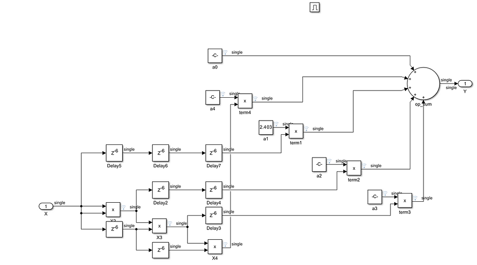
y = 2E-09x4 - 4E-07x3 + 0.011x2 + 2.403x - 251.26
To implement this using Simulink is straight forward we can use the HDL coder product, constant and sum block. We may also need to use some of the delay blocks to ensure the data aligns as it flows though the system.

To ensure I could implement the block as an AXI streaming element, I implemented the design within a enabled subsystem. The valid input and output can be used as part of the AXI Stream interface.

Running the simulation results in the expected temperature 23.5004 C being calculated correctly for a given input from the ADC.

The next step was to generate the IP core, for this project I used Matlab Simulink 2024b. When the code is generated we want to ensure HDL Coder, leverages the DSP58 elements within the Versal device.
To make sure this occurs, the first thing we need to do is set the hdl tool path, which looks like the command below. We need to give the location of the Vivado installation we wish to work with.
hdlsetuptoolpath('ToolName','Xilinx Vivado','ToolPath','C:\Xilinx\Vivado\<version>\bin\vivado.bat');Once this has been completed within the HDL Coder settings we can target the Versal edge device in this case the XCVE2302 along with a target frequency of 400 MHz.

On the floating point tab ensure the option AMDFloatingPointOperators is selected for the vendor specific floating point library option is set.

We can then generate the RTL which will show the expected resource utilisation in the output report from Simulink.
Along with the IP Core prepackaged which can be included within a project we are also provided with a Vivado project which we can use to synthesise and implement the results to obtain a resource estimation
Opening the project will show the floating point IP cores instantiated to use the DSP58 in FP32 mode.

To do a trial synthesis we are can, set the mode in synthesis to out_of_context and run the implementation to obtain a resource indication.

Opening the results of the implementation shows the DSP58 has been used in the FP32 mode, as a result the resources required for implementation is significantly reduced compared to the original approach using IEEE floating point libraries.

It only took a few minutes to create this solution which is also good and of course the code is technology independent.
I will come back to this in a few weeks and explore using the Vivado IP blocks directly and direct instantiation in RTL as I think exploring the different ways we can work with the DSP58 in FP32 mode is interesting and may come in useful in the future.
Workshops and Webinars
If you enjoyed the blog why not take a look at the free webinars, workshops and training courses we have created over the years. Highlights include
Upcoming Webinars Timing, RTL Creation, FPGA Math and Mixed Signal
Professional PYNQ Learn how to use PYNQ in your developments
Introduction to Vivado learn how to use AMD Vivado
Ultra96, MiniZed & ZU1 three day course looking at HW, SW and PetaLinux
Arty Z7-20 Class looking at HW, SW and PetaLinux
Mastering MicroBlaze learn how to create MicroBlaze solutions
HLS Hero Workshop learn how to create High Level Synthesis based solutions
Perfecting Petalinux learn how to create and work with PetaLinux OS
Boards
Get an Adiuvo development board
Adiuvo Spartan 7 / RPi 2040 Embedded System Development Board
Adiuvo Spartan 7 Tile - Low Risk way to add a FPGA to your design.
Embedded System Book
Do you want to know more about designing embedded systems from scratch? Check out our book on creating embedded systems. This book will walk you through all the stages of requirements, architecture, component selection, schematics, layout, and FPGA / software design. We designed and manufactured the board at the heart of the book! The schematics and layout are available in Altium here Learn more about the board (see previous blogs on Bring up, DDR validation, USB, Sensors) and view the schematics here.


Comments