
One of the great things about writing this blog (there are many) is when people as real world questions as they need help. Last week, some one asked me a question about how the Zynq and MicroBlaze can work together, the question asked was.
“Adam! On a zynq 7020 how can I reset a microblaze to start from the top of main with a signal from the processing system”
At first this seems pretty straight forward, but thinking about it a little more I realised there were a few nuances, which would make for an interesting blog.
The architecture is simple a Zynq 7000 device configured to run a bare metal application, while a MicroBlaze V processor is implemented within the programmable logic.
When the MicroBlaze V is reset it will start executing the program which is contained within its local memory bus BRAM.
At the simplest level we are going to connect one output from the Zynq 7000 using an AXI GPIO to reset the MicroBlaze V and restart its execution. To show the MicroBlaze V is executing its application it will flash LEDs on the Arty Z7-20 target board which I am using the prototype the example.
Architecting the system requires a little thought as I wanted the MicroBlaze V to be able to run its application immediately the PL is configured and not need the configuration of the PS.
This will allow us to debug the application running in the MicroBlaze first without the need to generate the PS application.
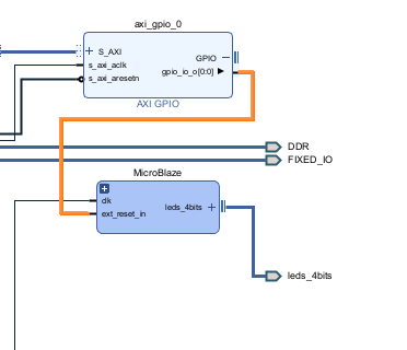
To achieve this I have created the design as below


The key points are the MicroBlaze V is clocked by the PL clock at 125 MHz, I use a clock wizard to reduce this to 100 MHz to clock the MicroBlaze V and its peripherals.

Configuring the MicroBlaze V to follow the microcontroller preset, using the block automation and enabling debug module. Will create a MicroBlaze V signals which will also provide the debug interface and processor reset system, without the external reset signal connected. It is this external reset signal which will be used to reset the MicroBlaze V, it will be connected to the Zynq AXI GPIO signal.
The Zynq AXI GPIO is configured to provide a single bit configured as an output and its default level is high. This is the reset INACTIVE state, as such the MicroBlaze V will not be reset, it will however power up and be subject to the GSR. As the clock wizard locks the reset to the MicroBlaze V will be cleared and it will start operation.


This means we are then able to develop the MicroBlaze V application, debug it on the Arty Z7-20 without the need to worry about the PS software being configured. We can then debug the MicroBlaze V as we would normally in this instance it is pretty simple code
#include "xparameters.h"
#include "xgpio.h"

XGpio led;

int main ()
{

    XGpio_Initialize(&led, XPAR_MICROBLAZE_AXI_GPIO_0_BASEADDR);
    while(1){

      XGpio_DiscreteSet(&led,1, 0xA);
      usleep(500000);
      XGpio_DiscreteClear(&led,1, 0xA);
      usleep(500000);
    };


}
For the design to work correctly and enable the MicroBlaze V code to be stopped and started under the control the PS. We do NOT want the MicroBlaze V to be connected to a debugging session otherwise following reset the processor will wait for execution commands.
Therefore the bit stream of the FPGA was updated to include the MicroBlaze V elf file. That way once the PL is configured you will see the MicroBlaze V executing and in this application the LEDs flashing.

We can then re-export the XSA and update the platform in Vitis Unified such that the updated bitstream is provided. This will enable the MicroBlaze V to execute immediately the PL is programmed and the clock locked.
Once the Platform has been updated we are then able to create the PS application this will toggle the reset line connected to the MicroBlaze V when any key is pressed over the terminal.
#include "xparameters.h"
#include "xgpio.h"
#include <stdio.h>

XGpio reset;

int main ()
{

    printf("Zynq Application\n\r");
    XGpio_Initialize(&reset, XPAR_XGPIO_0_BASEADDR);

    while(1){
        printf("Press any key to halt MB\n\r");
        char c = getchar();
        c = getchar();
        c = getchar();
        XGpio_DiscreteClear(&reset,1, 0x1);

        printf("Press any key to start MB\n\r");
        c = getchar();
        c = getchar();
        c = getchar();
        XGpio_DiscreteSet(&reset,1, 0x1);
    };
}
You can see the example running in the video below, with the MicroBlaze V stopping and started as instructed.
Of course if you wish to do more complex applications with the PS and MicroBlaze V then you should be looking at the OpenAMP but this provides a simple solution and hopefully answers the question.
The project is uploaded here
Workshops and Webinars
If you enjoyed the blog why not take a look at the free webinars, workshops and training courses we have created over the years. Highlights include
Upcoming Webinars Timing, RTL Creation, FPGA Math and Mixed Signal
Professional PYNQ Learn how to use PYNQ in your developments
Introduction to Vivado learn how to use AMD Vivado
Ultra96, MiniZed & ZU1 three day course looking at HW, SW and PetaLinux
Arty Z7-20 Class looking at HW, SW and PetaLinux
Mastering MicroBlaze learn how to create MicroBlaze solutions
HLS Hero Workshop learn how to create High Level Synthesis based solutions
Perfecting Petalinux learn how to create and work with PetaLinux OS
Boards
Get an Adiuvo development board
Adiuvo Spartan 7 / RPi 2040 Embedded System Development Board
Adiuvo Spartan 7 Tile - Low Risk way to add a FPGA to your design.
Embedded System Book
Do you want to know more about designing embedded systems from scratch? Check out our book on creating embedded systems. This book will walk you through all the stages of requirements, architecture, component selection, schematics, layout, and FPGA / software design. We designed and manufactured the board at the heart of the book! The schematics and layout are available in Altium here Learn more about the board (see previous blogs on Bring up, DDR validation, USB, Sensors) and view the schematics here.
Comments